|
|
Post by Dillzio on May 7, 2010 11:54:31 GMT 1
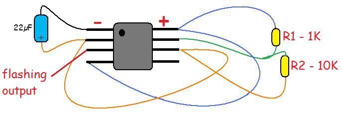
Nice work! Thanks for all the inspiration guys, I've got some good ideas on where I want to place my lights now. I just cooked my super cool red flashing beacon by hooking it up to 12v instead of 3v :-( Luckily they're only $2.20 delivered from Hong Kong so I've got another two on the way. I've cut into the foam plate under the plane to mount the circuit board very neatly into that.
I may have difficulty getting it to run off of 12v because it doesn't run off a constant amperage, it draws about 40ma with all the lights on, which will require a 220ohm resistor, but when only one light is on at a time it draws about 8ma, which would need 1K resistor. Perhaps it would be better to run it off the 5v BEC, so it would require 125-625ohms, then I could pick something inbetween and just hope it works.
While I appreciate the idea of having a seperate power supply for the beacon, so if the plane's electrics fail at night I can still find it with the beacon, but I really don't want to be carrying extra batteries and the battery case. Also, I'd have to have the batteries and light integrated into a single unit, so I wouldn't be able to mount it the way I want with the circuit board on the bottom of the fuselage. Perhaps a 3v lithium button battery would be OK, but I don't think the battery life would be all that great.
The other thing I'm considering is using the LEDs and circuit board from the one beacon I've got, since the LEDs still work, I've just cooked the IC. I could then just have the lights flashing from a 555-timer and I'd get to run everything off the main power.
Any thoughts?
|
|
|
|
Post by ginginho on May 7, 2010 13:55:58 GMT 1
Why not just power them with a couple of rechargeable AA's? They weigh next to f**k all when compared to the rest of the SC.
|
|
|
|
Post by Dillzio on May 16, 2010 5:19:01 GMT 1
My nav lights project is coming along nicely. I've wired two of the super bright wedge LEDs in series for the red, and green nav lights on the wings. I'm having these pointing outwards from the wing on a 45 degree angle, both pointing downwards, and one pointing front and one back. For on top of the wing, I wanted some red and green flashing LED beacons, but the normal flashing LEDs from the electronics shop were really dim. The solution I found was to also buy a normal superbright LED (at least 10,000mCD) and wire it up with the flashing LED in series. The flashing LEDs seem to have a resistor built into them with the timing circuit, so they can run straight off the 12v, but I ran a 30ohm resistor in series with them to drop the power down just a bit. I've also taken one of my white superbright ebay LEDs and hooked it up to a 555-timer to make a flashing strobe for the battery box, I can upload my circuit diagram of how to wire up the 555-timer for about 1.5hz if anyone's interested. I used all recycled wiring for this, getting some from a telephone cord, some from a network cable, and some from a USB cable. The USB wiring is really flexible, the telephone cable is a lot more rigid and a tiny bit lighter, and the network cable is thicker and heavier, and still flexible, but since it's thicker it's not as flexible as the USB wiring. I used some telephone wire for the 555-timer and it was a nightmare, the wire kept wanting to spring straight and pull the ends out of the circuit board. Also, with the superbright RED leds I got from ebay, it turns out that the two red globes were different - one is brighter than the other. They both have these small dots that the light comes from in the middle, one of them has two and the brighter one has three. I've emailed the seller to tell him they don't match, and see if he can send me out another of the brighter ones. I'll post some pics as soon as it all starts coming together. Here's how I wired up the 555-timer.  update if you make a timer like this, play around with some different values on a 555 timer to figure out what resistance you should use. I think using 10k resistors for R1 and R2 works well. |
|
|
|
Post by Dillzio on May 17, 2010 9:50:49 GMT 1
Here's a sneak preview of my new navlights, I couldn't contain myself any longer! The video's still processing, it should start working within a couple of hours.
I've cut into the foam and mounted the lights in there, so it looks real neat and will be more aerodynamic.
|
|
|
|
Post by charliebrown on May 17, 2010 11:37:04 GMT 1
That's cool! Any still pictures of it (the components and wiring)?
|
|
|
|
Post by Dillzio on May 17, 2010 12:37:18 GMT 1
I can take some pics tomorrow, so far it's just some wire from a network cable, the LEDs from ebay, a bit of solder to connect it together, and a few holes poked in the foam to make it nice and neat. I've just started putting in some channels for the wiring with a hot wire cutter I made from an old soldering iron, but got interupted by the GF so I'll have to finish it later.  I'm being sent out some more red LEDs from the ebay seller, because one of the ones I got was dimmer than the other. Once I've got the replacement I can get that together and installed too. Oh, and I've been doing some reading on how to make a simple voltage regulator so I can run the 3V flashing red beacon off the 5V BEC. It turns out that you can achieve a simple low current voltage drop of 2.1v by wiring three standard signal diodes in series, each diode drops the voltage by .7v :-) |
|
|
|
Post by charliebrown on May 18, 2010 19:31:20 GMT 1
I'm looking forward to see what this looks like when it's finished.
|
|
|
|
Post by tdemps24 on May 21, 2010 3:37:59 GMT 1
Just finished my Nav lights on my super cub. Bought the lights from rc-lights.com. My cub has 10 LEDs altogether. Wing has ted and green and strobes. 2 landing lights mounted right under cowl. Red strobes in the middle top and middle bottom fuselage. Strobe white and rear under tail and solid white and rear top fuselage. Didnt know how to post video to the forum so I uploaded it to youtube. Forgot to tell you guys that these lights can be turned on or off with a available channel. Got mine set up to be controlled by the gear channel on my DX6I. You can check it out here. www.youtube.com/watch?v=TFysiyovWWI |
|
|
|
Post by charliebrown on May 24, 2010 16:45:00 GMT 1
Nice job!
|
|
|
|
Post by Legot on May 25, 2010 2:06:27 GMT 1
Flashy!
|
|
|
|
Post by Dillzio on Jun 4, 2010 9:26:23 GMT 1
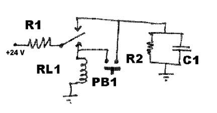
Hey gang. I've been wondering if I can find a way to have my receiver controlled switch running off the same channel as the flaps, and was hoping for some new ideas. I see a lot of people say they run their lights off the gear channel of their DX6is I was curious, is the gear channel one of the 6-channels on the receiver, or is there an extra on/off channel for the landing gear? I'm using the HobbyKing T6A, and if I get my way and have each ailerons on a seperate channel, I won't have a channel free for my receiver controlled switch that I planned to run my lights with, so I'm trying to figure out how to run it off the flaps channel. This particular switch is ON when it receives over +50% and off when it receives under. First thing I'm wondering is, if I set the sub trim to +40%, would that make it so that the switch would only need +10% to activate? I'm not too sure about how the sub trim feature works. I'm trying to make it so that if I 'pulse' the flaps to spoilers momentarily it will switch of the lights. The other thing I'm trying to figure out is how to make it so that the lights will switch on with a pulse from the switch, rather than a continuous signal? Does anyone happy to know of an easy design for a latching switch? I've found this one here but I'm having trouble interpreting it: www.oldradio.com/current/pushon-pushoff.htm is that meant to be an SPDT relay, with one of the outputs set to feed itself to hold itself open? I found the original circuit diagram here: www.hottips.org/kx00051.html |
|
|
|
Post by Dillzio on Jun 18, 2010 10:24:34 GMT 1
Though I'd post my most recent progress regarding the navlights project. I've given up on using that flashing bicycle beacon, I got sick of blowing the things. I blew the third one the other day when it was hooked up in a way that should have been OK, but I think it's a particularly fragile piece of electronics - it has an extremely tiny IC which is quite complex in it's operation. On the plus side though, those ebay bike beacon lights are an extremely inexpensive source of super bright red LEDs. They use 5 red, clean lens LEDS, which, as near as I can figure, run at 2.0v nominal and 20ma, and are about 12Kmcd brightness, I find that by putting 25ma-30ma through them (individually) they work beautifully. They cost $2.50 each from the electronics shop, but you get five of them in the flashing beacon light which also costs $2.50. So, I've made my own flashing beacon out of the LEDs from the other unit on a little strip of veroboard cut to size so it will fit in the same slot I cut out for the other beacon. I've chosen to wire all of the LEDs in parallel, but this presents another small problem when it comes to choosing the right resistor to do the job. As mentioned earlier, a good way of finding the right resistor for a LED is to hook the LED up in series with a 500K pot (variable-resistor), and measure the voltage across the LED as you slowly turn the resistor down. When you achieve the correct voltage for the led, you measure the resistance across the pot and that will tell you the correct resistance value you need for the LED. THIS DOES NOT WORK FOR LEDs IN PARALLEL!!! Learn from my mistake on this one fellas! I could crank a single one of these LEDs up to 2.3v without it blowing, but in an array of 5 they blew while only reading 2.11v! I had everything working nicely on a prototype board, but I didn't have a resistor that was rated to a high enough watt value to bleed off all the heat that's generated when you drop 12v down to 2v, so I hooked up a bunch of LEDs in parallel in a way that added up to the resistance I was trying to achieve. I got the 5 LEDS running nicely off of 60 ohms resistance, and it was working fine running from the 555-timer output and running directly from the battery. The next day I went to the electronics shop to buy some 1watt resistors (i was using two of them, to give me 2 watts of power dissipation). I get home, hook it up, measure the LED voltage as 2.1v, everything looks sweet, then the LEDs started going out one by one, they got burnt out. It turns out that if you're using resistors that aren't rated to the proper heat capacity, when they heat up their resistance increases. You can actually see this for yourself if you measure the amps running through the circuit with the over loaded resistor, the maths don't add up... I measured 120ma going through the LEDs, which was 10.3v (from a 555 timer and a signal diode) through a 60ohm resistor. 120ma @ 10.3v would have a resistance of 85ohms, so my over loaded resistors were actually offering 25ohms more resistance under load than what it read when I measured it with the multimeter. So, once I hooked it up with resistors that of the proper power rating it got a lot less resistance than the little resistors were putting up, and cooked my LEDs :-( If you want to work out the correct resistance for LEDs in parallel, you do it like this: R=(v1-v2)/I where V1= power supply voltage V2= LED voltage I= current in amps (in this case, say 22ma per LED, multiplied by 5 LEDs) R=(10.3-2)/0.110=75ohm When I hooked my LEDs up to the 11.2v lipo through the 60ohm resistor, each LED saw (11.2-2.1)/60= 30ma, which in this case was apparently enough to blow it. So, moral of the story, LEDs in parallel should only be run at their nominal ratings, and you need to calculate the right resistor for it, you can't measure it. Another hot tip, those Super bright LED wedge globs that i'm using, they run at 6.2v each. That means that you can hook two of them up in series and run them without a resistor. I got some more on ebay cos I wanted to get some of the 1.5w ones, which are brighter. I got the red ones installed today, but I'm still waiting on the green ones to be delivered. I hope this information serves to help someone else in the future, cos writing it all out has taken ages. Still, at least it will form a handy reference for myself for 6 months down that track when I've forgotten all this again  I should have the navlights finished by next week, i'll post some pics. I've got some red and green LED strips off of ebay for it too, which I planned to put either side of the fuselage, but now that I've got them I'm not sure I want to use them. They make it look a bit less like a plane with navlights and more like a neon christmas tree. Would be good for viability though. Decisions decisions... |
|
|
|
Post by john66 on Jun 18, 2010 11:57:57 GMT 1
|
|
|
|
Post by ginginho on Jun 18, 2010 14:34:53 GMT 1
They look pretty cool John. As for having them switchable, wouldn't it be possible to have the power line to them linked up via a micro switch that is activated by a servo on a spare (e.g. landing gear?) channel? That should be fairly simple to achieve and gives the option of turning them on mid-flight. Do you any idea of what sort of current draw they need. I may have a suitable switch somewhere from my days of fixing cashpoints (ATMs). I might get a set for the TS, that would look nice lit up! |
|
|
|
Post by john66 on Jun 18, 2010 14:46:16 GMT 1
Do you any idea of what sort of current draw they need. I may have a suitable switch somewhere from my days of fixing cashpoints (ATMs). I might get a set for the TS, that would look nice lit up! The leaflet says the following input voltage 4-6 V Current 30mA The first set I received one of the white strobes didnt work. I sent it back to the GC returns address about 1 week later I got an email telling me the strobe had been wired the wrong way, 2 days later I received the working set. I have no idea whether it was a replacement or my original one fixed. If you fancy a set I'd be quick cos when I last looked there were only 4 in stock and looking at all the comments it seems like they stay out of stock quite a while. I agree it shouldnt be too hard to implement a switch. John |
|


