Post by Britpilot on Feb 3, 2010 18:40:22 GMT 1
Carbon Fibre wing spar, LED nav lights and Carbon Fibre rigid wing strut mod.
This post is rather long with lots of pictures so I have posted it in three parts.
Part 2 can be found here: supercubclub.proboards.com/index.cgi?board=tt&action=display&thread=2793
Part 3 can be found here: supercubclub.proboards.com/index.cgi?action=display&board=tt&thread=2791&page=1
Part 1. Carbon Fibre wing spar, LED navigation and landing lights.
For some time I have been concerned that my advancing aerobatics with my SCLP (especially my attempts to fly inverted!) might overstress the wing. So after reading various posts on how to add a strengthening spar to the wing I decided to embark on this project. As I fly a lot at dusk I have also wanted to add LED navigation lights as and aid to flying the airplane and of course because I thought it would look cool!
I decided to use 5.3mm OD x 3.4mm ID carbon fibre tube for the spar. I cut a groove in the wing 60mm back from the leading edge at the thickest part of the wing chord. I used a circular table saw (I got that ideas from one of Flydivers excellent posts) to cut the groove just wide and deep enough that the CF tube would sit in it snugly without binding. The longest CF tube I could get at my local hobby shop was 1016mm (40”). I cut this in half and although the cut lengths would not reach all the way to end of the wing they would reach to within 90mmof the wingtip and would give more than adequate stiffening. I used a piece of 6.35mm (1/4”) OD alluminium tube 100mm long for the centre joining section and bent this carefully in the middle to the wing dihedral angle. I am not going to add ailerons to this wing so I kept the stock dihedral angle.
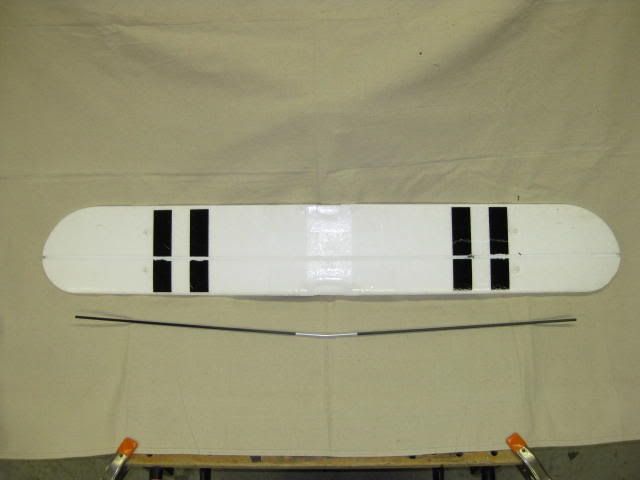
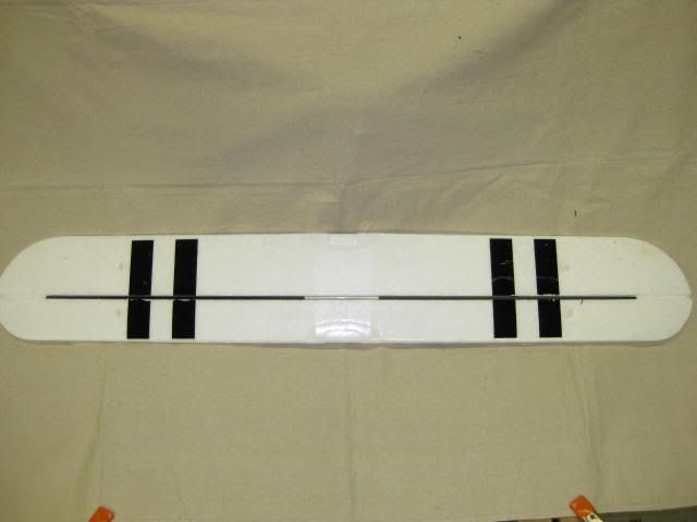
I epoxied the two CF tube pieces into the alluminium center section. After this had set I glued the wing spar assembly into the groove in the wing being careful to center the spar and keep the spar snug in the cut groove in the wing. (This is important as you need to keep the dihedral angle equal on both sides.) I used painters tape to keep it in place. I completely encapsulated the center section of the spar in epoxy as this is area is subject to the largest bending loads. To keep the weight down (epoxy is heavy!) I just bedded the spar in epoxy in the rest of the wing. Once the epoxy had set I filled the rest of the groove with white Gorilla Glue. I used a little to much though and despite my attempts to keep it in place with painters tape and “vent” gaps the darned stuff expanded so much it lifted the tape off! After the GG had finally set I had to carefully trim off the surplus GG and sand the groove flush with the wing.
With the wing spar in firmly bonded in place it was time to work on the LED lights.
A quick LED 101 for those not to familiar with LEDs. Every colour uses a different voltage and they need a resistor in series with the LED to reduce the LIPO battery voltage. Connect a LED direct to a 12+ volt LIPO and the LED makes a funny smell and dies! The MCD rating of a LED is the brightness (1000MCD = 0.1 candle power) Anything over 1200 mcd is nice and bright! LEDs come in various sizes (I used all 5mm diameter) and viewing angles. The narrower angle gives you more of a beam and I used narrow angle LEDS for my landing lights.
I decided to wire each LED in parallel with its own resistor as series wiring does not work with different voltage LEDS. The red, green, blinking red and white tail LEDs I got from Super Bright LEDs at: www.superbrightleds.com. The two landing light LEDS I bought at Radio Shack.
Here is the LEDs and the resistors I used.
Part #/ Colour & location/MCD/ View angle/Volts, min & max/Resistor used
RL5-R12120 Red/Port wingtip. 1200. 120. 2.0/2.4. 470
RL5-G16120 Green/Starboard wingtip. 1600. 120. 3.0/3.8. 330
RL5-W15120 White/Tail. 1500. 120. 3.0/3.8. 330
RL5-BR2020 Blinking Red/Vert Stabilizer. 2000. 20. 3.0/10.0. 330
276-0017 White/Landing lights. 7000. 30. 3.0/3.6. 220
I calculated the resistor size by connecting the LED to a 3s LIPO with an adjustable 1KΩ potentiometer in series and a digital voltmeter connected to the LED connecting wires. I started with the potentiometer at max resistance and gradually decreased the resistance until I had max voltage for the particular LED as measured on the voltmeter. I then disconnected everything and measured the resistance across the potentiometer terminals. I then chose a resistor that was as close to this as I could find, going for a higher resistance rather than lower. I could have just used ohms law but I prefer a practical way!
I used telephone wire for the wing LED wiring. I pulled the wires out of 2metres of the six wire telephone cable used for internal hard wiring. These individual wires are very light, insulated in different colours and have a single strand solid copper conductor. I spun three wires 750mm long together using an electric drill. Black, red & blue for the port wing. Black green & blue for the starboard wing. I like my wings to be smooth as possible so I made a groove for the LED wiring approx 4mm deep in the underside of the wing with a fine tip soldering iron and a straight edge. (I had thought of inserting my LED wiring in the same groove as the CF wing spar but decided that replacing or repairing the wires one day would be awkward if I did that.) I drilled a 6mm hole through the leading edge of each wing 200mm in from the tip and epoxied a 50 mm long piece of 7mm OD plastic tube in the hole as a holder for the LED. As my CF spar did not reach the end of the wingtip I used the empty spar groove for the nav light mounting tube.
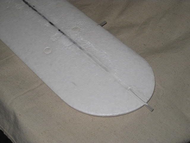
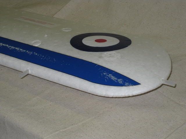
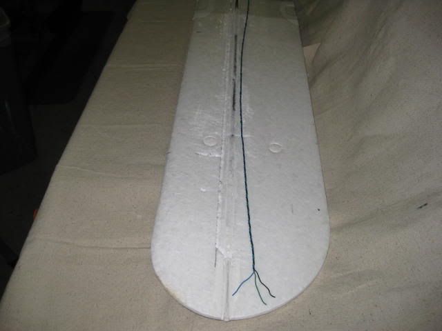
I held the wiring in place in the groove by “tacking” it with blobs of hot glue and stuck the LEDs in their mounting tubes with clear silicone. I placed the four resistors under the centre section of the wing where they would be inside the fuselage. I bought all the positive and neutral wires together into the male part of a two pin connector I bought at Radio Shack. This was rather fiddly with lots of delicate soldered splices and careful use of heat shrink tubing. I used clear packing tape to keep all the wiring in place making sure the resistors were not covered to allow cooling air to circulate as they can get a little warm.
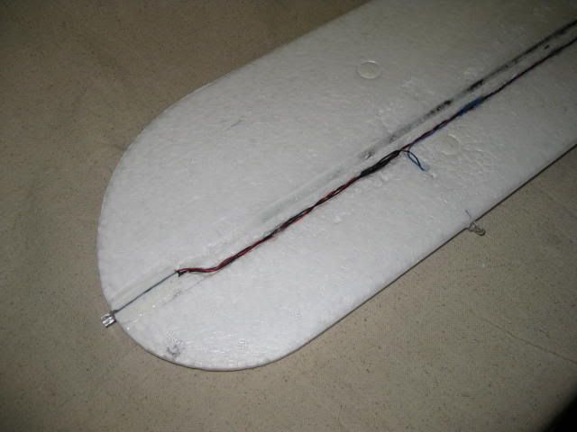
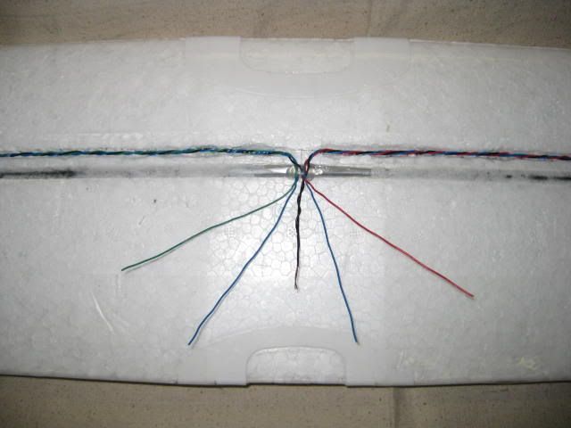
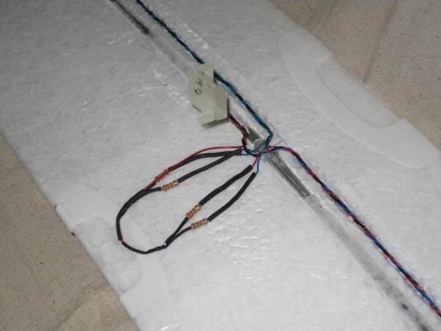
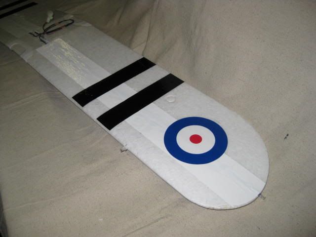
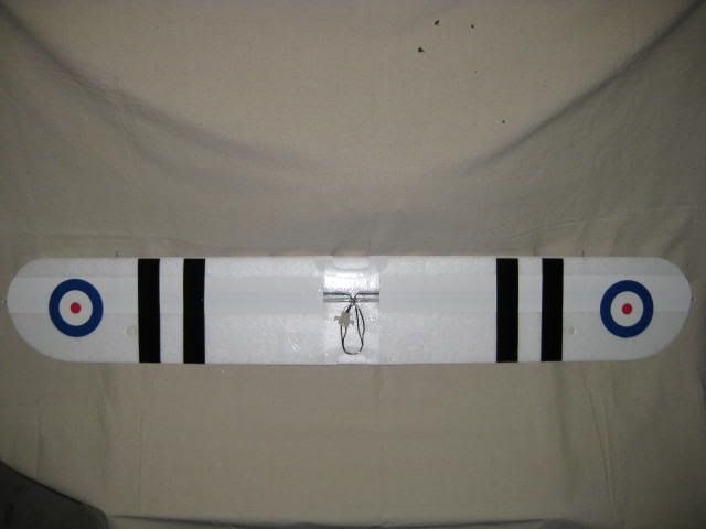
After testing all that my wiring was correct and all the LEDS lit up correctly I covered the wing spar and LED wiring groove with a 52mm wide band of white “MonoKote” self adhesive plastic covering. (First time I have used this. It’s an excellent product!) I like the two black stripes on the bottom of the wing for orientation in flight and I replaced these with two stripes cut from black self adhesive MonoKote. My RAF roundels which are part of my new pseudo Royal Air Force trim finished the job. The bottom of the wing turned out very flush and smooth as I had planned.
This post is rather long with lots of pictures so I have posted it in three parts.
Part 2 can be found here: supercubclub.proboards.com/index.cgi?board=tt&action=display&thread=2793
Part 3 can be found here: supercubclub.proboards.com/index.cgi?action=display&board=tt&thread=2791&page=1
Part 1. Carbon Fibre wing spar, LED navigation and landing lights.
For some time I have been concerned that my advancing aerobatics with my SCLP (especially my attempts to fly inverted!) might overstress the wing. So after reading various posts on how to add a strengthening spar to the wing I decided to embark on this project. As I fly a lot at dusk I have also wanted to add LED navigation lights as and aid to flying the airplane and of course because I thought it would look cool!
I decided to use 5.3mm OD x 3.4mm ID carbon fibre tube for the spar. I cut a groove in the wing 60mm back from the leading edge at the thickest part of the wing chord. I used a circular table saw (I got that ideas from one of Flydivers excellent posts) to cut the groove just wide and deep enough that the CF tube would sit in it snugly without binding. The longest CF tube I could get at my local hobby shop was 1016mm (40”). I cut this in half and although the cut lengths would not reach all the way to end of the wing they would reach to within 90mmof the wingtip and would give more than adequate stiffening. I used a piece of 6.35mm (1/4”) OD alluminium tube 100mm long for the centre joining section and bent this carefully in the middle to the wing dihedral angle. I am not going to add ailerons to this wing so I kept the stock dihedral angle.


I epoxied the two CF tube pieces into the alluminium center section. After this had set I glued the wing spar assembly into the groove in the wing being careful to center the spar and keep the spar snug in the cut groove in the wing. (This is important as you need to keep the dihedral angle equal on both sides.) I used painters tape to keep it in place. I completely encapsulated the center section of the spar in epoxy as this is area is subject to the largest bending loads. To keep the weight down (epoxy is heavy!) I just bedded the spar in epoxy in the rest of the wing. Once the epoxy had set I filled the rest of the groove with white Gorilla Glue. I used a little to much though and despite my attempts to keep it in place with painters tape and “vent” gaps the darned stuff expanded so much it lifted the tape off! After the GG had finally set I had to carefully trim off the surplus GG and sand the groove flush with the wing.
With the wing spar in firmly bonded in place it was time to work on the LED lights.
A quick LED 101 for those not to familiar with LEDs. Every colour uses a different voltage and they need a resistor in series with the LED to reduce the LIPO battery voltage. Connect a LED direct to a 12+ volt LIPO and the LED makes a funny smell and dies! The MCD rating of a LED is the brightness (1000MCD = 0.1 candle power) Anything over 1200 mcd is nice and bright! LEDs come in various sizes (I used all 5mm diameter) and viewing angles. The narrower angle gives you more of a beam and I used narrow angle LEDS for my landing lights.
I decided to wire each LED in parallel with its own resistor as series wiring does not work with different voltage LEDS. The red, green, blinking red and white tail LEDs I got from Super Bright LEDs at: www.superbrightleds.com. The two landing light LEDS I bought at Radio Shack.
Here is the LEDs and the resistors I used.
Part #/ Colour & location/MCD/ View angle/Volts, min & max/Resistor used
RL5-R12120 Red/Port wingtip. 1200. 120. 2.0/2.4. 470
RL5-G16120 Green/Starboard wingtip. 1600. 120. 3.0/3.8. 330
RL5-W15120 White/Tail. 1500. 120. 3.0/3.8. 330
RL5-BR2020 Blinking Red/Vert Stabilizer. 2000. 20. 3.0/10.0. 330
276-0017 White/Landing lights. 7000. 30. 3.0/3.6. 220
I calculated the resistor size by connecting the LED to a 3s LIPO with an adjustable 1KΩ potentiometer in series and a digital voltmeter connected to the LED connecting wires. I started with the potentiometer at max resistance and gradually decreased the resistance until I had max voltage for the particular LED as measured on the voltmeter. I then disconnected everything and measured the resistance across the potentiometer terminals. I then chose a resistor that was as close to this as I could find, going for a higher resistance rather than lower. I could have just used ohms law but I prefer a practical way!
I used telephone wire for the wing LED wiring. I pulled the wires out of 2metres of the six wire telephone cable used for internal hard wiring. These individual wires are very light, insulated in different colours and have a single strand solid copper conductor. I spun three wires 750mm long together using an electric drill. Black, red & blue for the port wing. Black green & blue for the starboard wing. I like my wings to be smooth as possible so I made a groove for the LED wiring approx 4mm deep in the underside of the wing with a fine tip soldering iron and a straight edge. (I had thought of inserting my LED wiring in the same groove as the CF wing spar but decided that replacing or repairing the wires one day would be awkward if I did that.) I drilled a 6mm hole through the leading edge of each wing 200mm in from the tip and epoxied a 50 mm long piece of 7mm OD plastic tube in the hole as a holder for the LED. As my CF spar did not reach the end of the wingtip I used the empty spar groove for the nav light mounting tube.


I held the wiring in place in the groove by “tacking” it with blobs of hot glue and stuck the LEDs in their mounting tubes with clear silicone. I placed the four resistors under the centre section of the wing where they would be inside the fuselage. I bought all the positive and neutral wires together into the male part of a two pin connector I bought at Radio Shack. This was rather fiddly with lots of delicate soldered splices and careful use of heat shrink tubing. I used clear packing tape to keep all the wiring in place making sure the resistors were not covered to allow cooling air to circulate as they can get a little warm.


After testing all that my wiring was correct and all the LEDS lit up correctly I covered the wing spar and LED wiring groove with a 52mm wide band of white “MonoKote” self adhesive plastic covering. (First time I have used this. It’s an excellent product!) I like the two black stripes on the bottom of the wing for orientation in flight and I replaced these with two stripes cut from black self adhesive MonoKote. My RAF roundels which are part of my new pseudo Royal Air Force trim finished the job. The bottom of the wing turned out very flush and smooth as I had planned.


